
In modern electrical and electronic engineering, clarity in circuit design is essential. Using the correct symbols, especially for solid state relays (SSRs), ensures that schematics are easy to understand and reduces the risk of errors during installation or maintenance. Mastering SSR symbols elevates both design quality and communication among engineers.
Enhancing Circuit Understanding Through Standardized Symbols
- Universal Recognition: The solid state relay symbol is widely recognized in the engineering community. Accurate use allows engineers, technicians, and students to immediately identify SSR components in a schematic without confusion.
- Simplified Troubleshooting: Clear symbols reduce the time required to trace circuits and diagnose issues, improving maintenance efficiency in complex systems.
- Effective Documentation: Correct representation of SSRs ensures documentation is professional and adheres to standard practices, which is crucial for audits, training, and collaborative projects.
Key Features of Solid State Relay Symbols
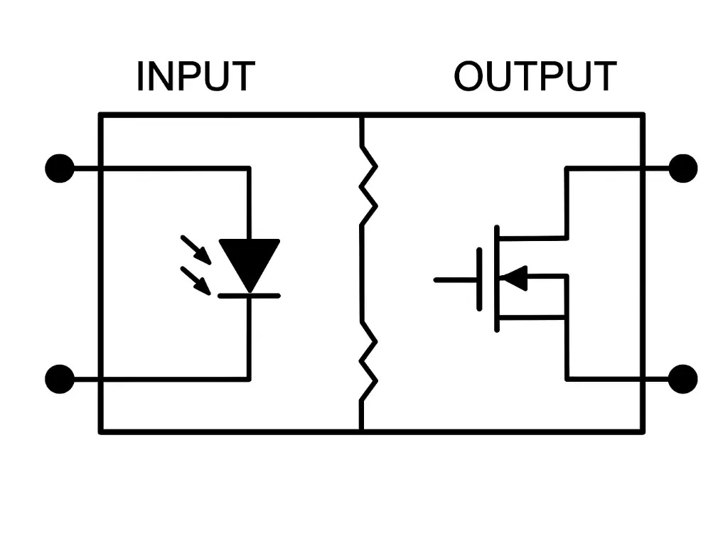
- Input and Output Distinction: SSR symbols clearly indicate the control input and the load output. This distinction helps in understanding how the relay switches and isolates circuits.
- Load Type Indication: Symbols often differentiate between AC and DC loads, helping engineers select proper circuit configurations and avoid misinterpretation.
- Opto-Isolation Representation: Many SSR symbols include a representation of opto-isolation, emphasizing safe electrical separation between control and power sides.
Benefits of Accurate Symbol Use in Schematic Design
- Improved Readability: Neatly drawn and standardized symbols prevent clutter and confusion, allowing schematics to communicate ideas clearly at a glance.
- Error Reduction: Correct symbols reduce miswiring risks, which is critical in high-speed or sensitive electronics where mistakes can cause significant downtime or damage.
- Enhanced Collaboration: Teams working on the same project can easily interpret circuit diagrams, leading to faster project execution and fewer misunderstandings.
Best Practices for Implementing SSR Symbols
- Follow Standard Guidelines: Adhering to IEC or IEEE schematic standards ensures that your diagrams are universally understandable.
- Consistent Orientation: Place symbols uniformly in schematics, maintaining input and output sides consistent across designs for clarity.
- Label Clearly: Include relevant parameters such as voltage ratings, load type, or control voltage near the symbol to enhance comprehension.
- Use Software Tools: Modern schematic design software supports standardized SSR symbols, minimizing manual errors and improving presentation quality.
Impact on System Design and Maintenance
Accurate SSR symbols not only enhance readability but also contribute to safer and more reliable system designs. Engineers can visualize interactions between components more effectively, supporting better predictive maintenance and faster system upgrades. By emphasizing clarity, well-drawn symbols streamline communication between design, testing, and field teams. Proper solid state relay symbol usage enhances system safety.
Conclusion
Integrating solid state relay symbols accurately in schematics is a fundamental practice for efficient engineering workflows. It ensures clarity, reduces errors, and promotes effective collaboration. Proper symbol usage transforms circuit diagrams from mere technical documents into precise, intuitive tools that advance both design and operational excellence.